Part C:

The AL7X Hex Beam

Updated 9/13/2013


And the winner is .... !

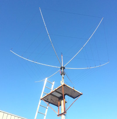
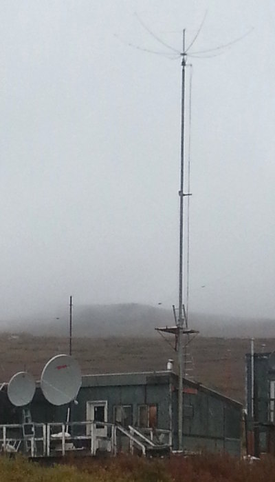
I ordered the a Traffie HB5xi Hex Beam.   shown at left under clear, blue skies at my QTH.

This antenna was $1,229.30 including USPS priority mail shipping. Not many antennas are US Mail shippable!

The picture at left was taken on 9/12/2013 at my own QTH. It is a pretty sight!


For less money, around $650, you can get the "Broadband" version of the hex, see K4KIO.

The differences are:

  • Traffie is smaller, 18' diameter vs 21 ft.
  • Traffie is somewhat lighter.
  • Traffie has 27% less wind area and twisting moment.
  • Both have good SWR across the band, but
  • The B.B. sustains the Front-to-Back ratio better over the band.
  • The Traffie is of better build quality (but the K4KIO is ok).

Broadband Hex antennas are also made by  DX Engineering   and NA4RR,  and there are a few kits out there as well. But I do recommend the K4KIO if you want a BB Hex.

My research revealed that an Aluminum 2-element tribander will be more brittle in the ice/wind; will have less gain than the Hex, and would only cover three bands (20-15-10) vs the Hex's 5 bands (20-17-15-12-10). A three element aluminum trap Tribander still covers only 3 bands, has much more wind area and weight, and has only a marginal gain advantage over the Hex.

The Traffie Hex's smaller size, reduced wind load etc. would also give it an advantage over the B.B. Hex in survivability here in my mountain valley QTH. The BB would not have survivability issues in downtown Nome, and is a perfectly viable alternative.

You can obtain a wealth of information in Understanding the Hexbeam by Steve, G3TXQ


Rotor and Rotor Plate

This is the rotor and mounting plate. Keith KL1CC welded it for me. The white, round steel has holes for bolting the rotor, and 8 holes in the periphery for guy ropes, and other dangables.

The pipe nipple sticking out to the left is welded to the rotor plate, and slides into the top of the MA-550 tower. Two large setscrews on the tower hold it in place.

The angle sticking out towards us will hold the top of the coax and rotor cables. Understand that managing cables on a crankup tower is somewhat more complicated than on a fixed tower!


Opening up the Boxes

The antenna came in two boxes. One about 15" square and 8" tall, and the other a long, skinny box about 8" x 8" x 5 feet.

At left is a picture of the contents of the long box; basically the spreaders and the center post.

The other box contains the mounting base plate, the antenna elements and other strings, and miscellaneous stuff.


Assembling the Kit

My son Tony at it. About 2 hours, nothing real challenging, but needs two pairs of hands.

The orange thingie is a military mast tripod hub, not part of the hex. I used it along with a piece of 1-1/4 pipe to hold the antenna at a convenient work height.

Assembly was like this:

  • Place hub plate on the temporary pipe.
  • Insert all six spreaders into the hub. They each come in two pieces.
  • One set of strings brings two spreaders up.
  • The other set of strings are placed.
  • Starting at the top, the 20 meter driven and reflector are strung. This gives the antenna its parabolic shape.
  • Then the 17, 15, 12 and 10 meter elements are strung.
  • Minor details follow, like the feedline stub.
 

Raising into Position

After assembly on 9/8, my #3 Daughter Kandie and Don Erickson KL2ZF took the antenna and placed it on top of the rotor, which I had previously placed on the tower.

You should know that this antenna is so light, it can be lifted with one hand. With some care, Kandie and I passed it up to Don, and he just dropped it into the rotor.

At the time this picture was taken, the cabling has not been connected.


Under Leaden Skies

On 9/11 Kandie, her boyfriend Gabe, myself, and Keith KL1CC connected the cables, dressed everything, and raised it up. Here you can see it at full height, all connected.

We took care to stuff all the coax and rotors connectors with teflon dielectric compound, and wrapping up all the joints with "Coax Seal." All chafe points in the cables are overwrapped with rubber hose.

For the curious, the two dishes are for my Dish TV, about 4' diameter, and the larger 7 footer is for Starband Satellite Internet as I do not have cable out here in the country.


Performance and Operational Details

The antenna performs beautifully. Here are some figures

  • 20 meter SWR: 1.4 @ 14,000, 1.1 from 14,050 up."
  • 17 meter SWR: 1.3 @ 18,068, 1.2 from 18.100 up."
  • 15, 12 and 10 meters: SWR: 1.4 at lower band edge, then 1.1 or less from 50 kHz up from the bottom.
  • I did not measure SWR above 28.6 mHz on ten meters.

That is impressive performance.

How does it work?

In a nutshell, simply fantastic.

Front to side and front to back ratio is very pronounced, and better than I ever got with an aluminum 2- and later 3- element trap tribanders back in 1972.

Listening to a South American Chilean station having a QSO with a Siberian station, I first aimed the beam at Chile. He was then S4 to S5. The Russian was about S5 as well. Turning the beam around, the Russian rose to S9+ and the Chilean station faded into the background.

Today, 9/12/13, I turned on my rig and had the beam pointed at the lower 48 states (due east). I could hear some Europeans coming in rather weak, S3 to S5. I swung the beam north towards Europe. The Europeans all came up to S9+ with pronounced auroral flutter. In short order I called a Swedish Station SM2EKM and exchanged 599+ reports. He was about 10db over S9 -- also called "pounding in." Although, the auroral flutter gave his signal a surreal sound.


Part A: The Tower
Part B: Temporary 20m Dipole
Part D: Aiming the HF Antenna
Part E: The ICOM IC-7410 Radio
Part F: AL7X goes Digital!
Return to XAlaska main page

Copyright 2013, Ramon Gandia