See also:
Part B: Temporary Dipole
Part A: The AL7X Tower and HF Station Project
Updated 8/5/2013
Back in 1972 I finaly made DXCC from Nome, and my radio gear back then consisted of a Swan 350, followed by a Yaesu FT-101 and Heathkit SB-200 1 kw linear amplifier.
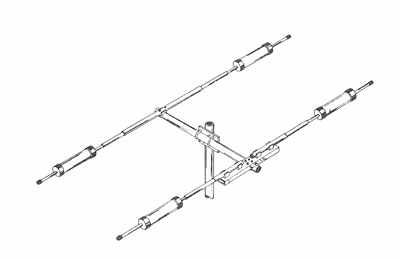
That station had, at first, a 35 foot pole with a 2-element beam and rotor, much akin to the Mosley TA-32 beam marketed today. It was replaced with a 102 ft self-supporting tower in 1981, with a 3 element tribander. That was some tower!
Alas, after my first divorce in 1983 I have not operated HF with any significance. Now, retired and again single, I plan to hit HF again.
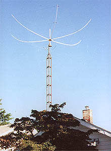
I do have a 100 watt Alinco DX-70 HF transceiver, but my antenna is rather poor: a 75/40 meter trap dipole which operates dismally on the DX bands: 30-20-17-15-12-10.
That is a situation I intend to rectify!
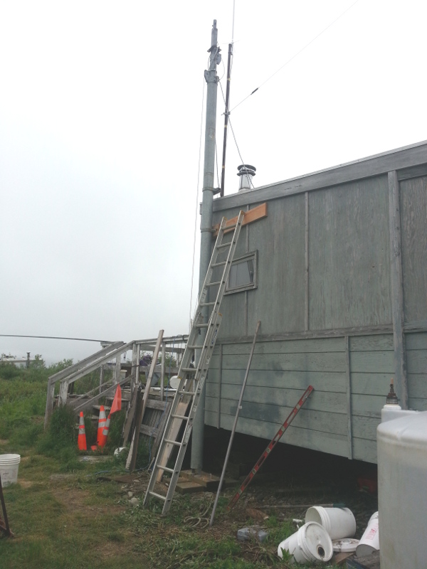
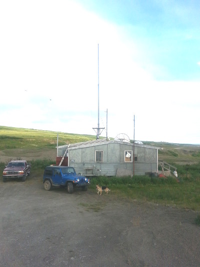
This is my U.S. Tower MA-550 crankup tower
going up.
July 20, 2013
The MA-550 is a self-supporting 55 foot tall crankup tubular
tower. I have previously owned this tower, and bought it
back last year.
The MA-550 supposedly requires no guy wires, but I can attest that in a good wind it will sway frighteningly with the various non-ham antennas I had on it about 12 years ago.
Therefore, what I propose to do is to put a set of non-metallic guys at the top. Synthetic Dacron rope is attractive; it cushions the wind gusts and should be perfectly adequate for a tower rated as freestanding.
This picture shows the entire tower. Look at the top and you will notice the three nested pipes that comprise this unit. The lower pipe is 6.5 inches diameter, followed by a 5 inch pipe, and at the top a 3-inch square tube. All are 20 ft long and overlap about 2.5 ft at full extension.
My number 3 daughter, Kandie, was instrumental in getting this tower put up. Previously, Keith KL1CC helped in getting the tower moved close to the base, and my son Tony and helper Zack assembled the base out of treated 3 X 12 lumber.
The wood portion of the house bracing was done by Autumn Falls, KL1CT. The steel portions by yours truly. See, I can actually get my hands dirty!
Hoisting the pipe from horizontal position where it was laying down, to vertical was accomplished by use of a Warn PullEZ, a handheld, cordless electric come-along. Push a button ... up it went without much trauma.
More details on the MA-550
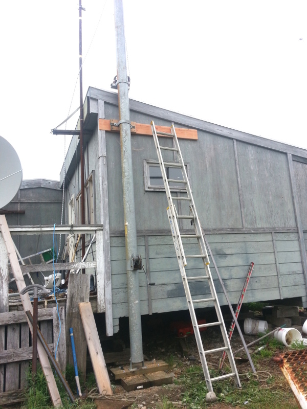
This is actually the better picture, but it does not show the very top of the tower where the nested pipes are visible.Here you can see several details:
- The hand crank winch.
- The wood pad for the base
- The wall bracket
The lower section is 6.5" steel tubing, about 3/16 wall; the middle is roughtly 5" tubing and the top section is 3" SQUARE tubing. At the very top of the square tubing is a one foot long 2" ID tubing to put rotors etc. on.
My hand winch is much deteriorated, and a replacement is on order from Amazon.com. It is only $120. I am also contemplating an electric 120 volt AC winch from Harbor Freight that has been used by hams for just this application. Handy if it has to be cranked down in the middle of night when the wind picks up!
At the time the picture was taken, on 7/21/2013, the pipe is not quite vertical. The hinge at the bottom will be unbolted, the pipe opendicularized, and half-inch thick, six inch long lags will replace the temporary puny lags there now. The base has to move less than one inch, yet, it is always important to keep the tower vertical!
You can't see it here, but that top bracket is backed from inside the house by a formidable wood and steel reinforcement. If the tower comes down, the wall will come with it. That means it is going to stay together, tight and snug (or I will be heating the outdoors!)
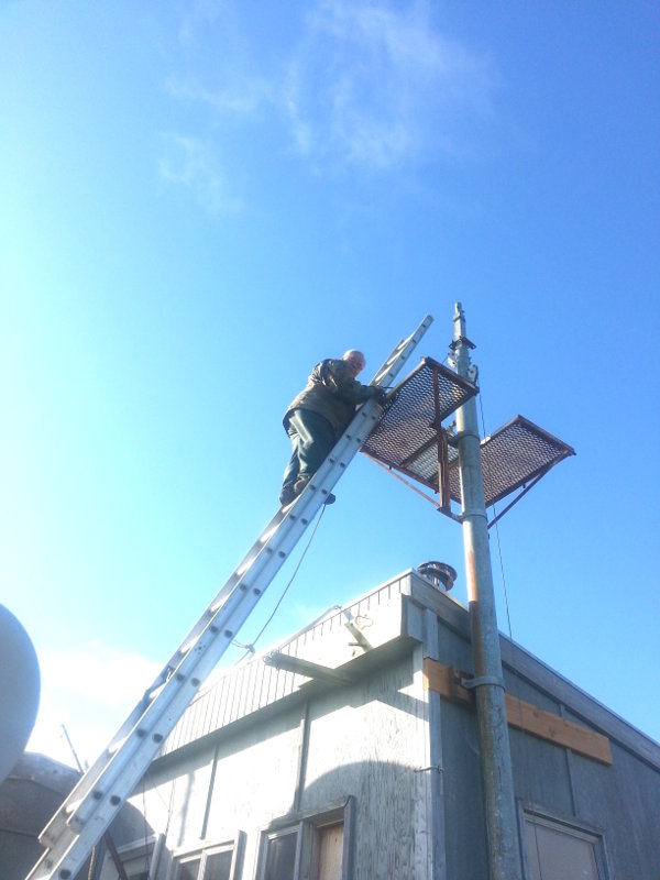
The Antenna Working Platform
7/25/2013
Here I am, climbing up to the working platform. Standing on the
platform, the antenna and rotor assembly will be about chest high.
This is a secure working environment, and makes antenna work
much easier and convenient.
Daughter Kandie and stepson Zachery helped me put this platform up today.
What is left to do?
Replacing the crankup winch with either the new manual winch or the electric one discussed above.
Safety checks and inspections on the structure and cable.
Guying the towertop with dacron rope. This is a non-stretch, UV resistant rope. While the mast is rated to be freestanding, the ropes will dampeng any swaying or vibration.
Conduit runs for my antenna coax and rotor cables. I may also run conduit for AC power to the electric winch. All these conduits will be under the house.
A grounding rod for lightning or athmospheric static.
Perhaps provision to haul up Christmas lights?
Work of Friday, 7/26/2013
Light duty day, but covered up several little details.
- Set the base of the tower so it is perfectly vertical.
- Per Electrical Code, put a ground rod at base of tower.
- Tightened all mounting bolts.
- On the base, replaced the 1/4 lags with 1/2 inch lags.
- An antenna pipe that was in the way with a VHF and one end of my 75/40 antenna was moved and reinstalled.
Work of Saturday, 7/27/2013
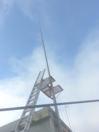
Today I merely extended the tower to its full height, 55 ft AGL. I am leaving it there to see how it acts in the wind/breeze. I hung a rope from the top to figure how guy lines, if needed, would be laid out.
Then I took the pictures, laid back and admired!
Note on August 5: even with wind this tower has been quiet. No banging or clanking. I was worried about this as it is bracketed to the house. A windstorm may be a different story ...